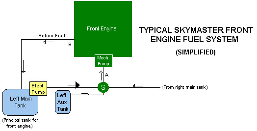
The drawing below shows only the fuel system for the front engine. It consists of the main tank and the separate auxiliary tank on the left wing, a fuel selector switch (the green circle with the S), the mechanical fuel pump driven by (and attached to) the engine, and the engine's fuel injection system (not shown). For the front engine, the left main tank is referred to as the "principal" tank; this is the baseline tank, used during take-off and landings (notice the larger/darker arrow), and this tank has an auxiliary electric fuel pump. Finally, there is the return fuel line which takes excess fuel and vapor back to the left main tank.
Notice that the fuel selector switch can be set to draw fuel from either of the tanks on the left wing (the main or the auxiliary), but it can also be set to draw fuel from the right wing main tank, which (as you probably have guessed) is the principal tank of the rear engine. So, the front engine has the two tanks, on the left wing, but in a pinch can draw from the right main tank.
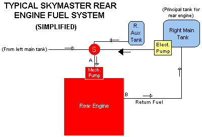
Let's look now at the fuel system for the rear engine as shown below. It is essentially the mirror image of the front engine fuel system, consisting of the main tank and the separate auxiliary tank on the right wing, plus a repeat of the items mentioned above (fuel selector switch, mechanical fuel pump, fuel injection system, and return fuel line). Again, it has a "principal" tank, which is the right main tank and has an auxiliary electric fuel pump. And like the front engine, the fuel selector switch can be set to draw fuel from either of the tanks on the right wing and also from the left wing main tank.
Now that you've seen the two separate systems, please return to the prior page (using your "Back" or "Previous Page" Browser button) and look at the drawing of the full system; you should find it much easier to understand.